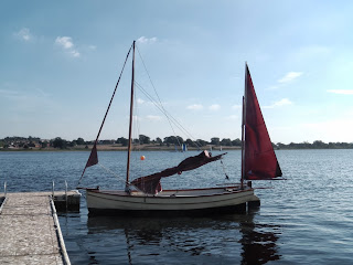
I'm building a boat to a design by Paul Fisher of Selway Fisher Design in the UK. The design is called "Able" and her vital statistics are: overall length 4.88m (16ft), beam 2m (6ft 6in) and design weight is 360kg (790lbs). You can read more about this design at http://www.selway-fisher.com/OtherDB.htm#KANE.

I intend to procede more slowly with this boat than I did with either of my other boat building projects (see links below on the right). This is, after all, a hobby and there are other things to do. So, updates to this blog might happen once every week or two. Come back and see.

If you would like to contact me please Click to Send me Email

Tuesday, 31 December 2013

Fore and Aft Decks

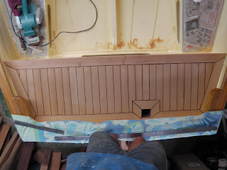
I like the idea and appearance of planked decks. Another benefit is that, with an oil finish, they will not be slippery. Some web searching turned up a couple of "how to" guides by builders of John Welsford Navigators. One is Barrett Faneuf's write up and the other is on Joel Bergen's blog. After studying both of these I made a start on the aft deck as it is smaller and an easier shape to deal with. Because I was working by trial and error I didn't take photos until the deck was finished. Here it is.

 
The result looks good to me and so I have made a start on the fore deck. The next photo shows the marking out for the pieces around the mast hole and samson post.

 
Before I cut the plywood deck I made a template from strips of scrap ply stuck together with hot melt glue. Fortunately I kept the side pieces and was able to reuse them to make templates of the margin planks at the sides. Here are the templates on the port side. These planks have to be in two pieces because my planking timber isn't wide enough to fit the curved shape. The joint is in the sunlight above the samson post.
 
 
Having cut all the pieces for the margin and the mitred pieces for the mast hole and samson post surrounds I started gluing them in place. This is a bit tricky because the planks tend to slip about on the epoxy. I'm using pavers to hold the planks down and being very watchful for signs of slippage until the epoxy begins to go off. We are having a run of 30+ degree days at the moment and so this doesn't take too long!
 

There are still two pieces of the side planks to add but, as you can see, the pavers get a bit crowded. Tomorrow I will glue them in and start filling in the space in the middle.


Saturday, 14 December 2013

Back in the Boat Shed

Towards the end of August I went to the UK for 10 weeks. While I was there I managed to meet up with a couple of people who own boats like the one I am building. First was John Sharpe and his SFD Able called Michy Lou for several hours sailing on Lake Ullswater on a cold, wet and windy day.


 Second was Nigel Modern and his SFD Kane (one plank less than Able) called Osprey for a warm sunny afternoon on a reservoir near his home.


I am very grateful to both these guys for the effort they put into taking me for a sail and can't thank them enough. These two days went a long way towards convincing me that I chose a good boat to build; normally you don't get to try the design you choose until you finish building the boat!

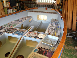
I've been home for 6 weeks and it is only in the last few days that I have restarted my Able project. I was jet lagged, I went away visiting friends, I went sailing and then, finally I started sanding the inside of the boat. Today I finished the sanding, taped and protected the areas where I don't want paint and put the first coat of primer on the inside of my boat. The tape and paper is for protection but also to remind me not to get carried away and paint parts that I shouldn't! Here are a couple of photos at the end of the day.


You can see that I am not painting the fore and aft decks and the seat tops. I am going to try and plank these areas. Definitely the decks and maybe the seat tops (if I like the decks).

That's it until I finish the painting. It might be a week or more before I post again because photos and words about paint drying aren't very interesting!


Sunday, 18 August 2013

Some Painting Done

Over the last couple of weeks I have varnished the gunwales - 6 coats of varnish over 2 coats of epoxy. The weather has been warmer than expect and I managed 2 coats of varnish most days.

When I painted the outside of the boat some months ago I sealed the plywood with 2 coats of epoxy. including the outside of the sheer strake. With the gunwale varnished I put 2 coats of undercoat and 3 coats of International Toplac on the outside of the sheer strake.

Here are three photos showing the state of the boat.


I'm going away for a while so this new paint work will have time to dry thoroughly. When I return the inside of the boat will be waiting for me. Lots more painting still to do!

Tuesday, 30 July 2013

Gunwales Complete

The gunwale capping strips are all in place and cleaned up. I fitted the quarter knees and a block on the transom to hold a rowlock for a sculling oar.  Having glued the capping strip on the transom I realised I would have to cut some of it away to provide clearance for the rudder stock to swing. Here is a photo showing the cut out. Also visible is the block for the rowlock and the portside quarter knee. I made these knees very strong. They are 5 x 10 mm thick laminations, not bent but blocked up like bricks in the corner. I will mount substantial cleats on these knees so I wanted them to be strong.


While I had the rudder mounted I saw that the skeg is thicker than the blade of the rudder by about 25 mm, it varies a bit because my skeg is tapered. This will cause some turbulent flow as the water passes from the skeg onto the rudder blade and I am thinking about adding some ply cheeks to the rudder below the waterline. This sill smooth the water flow and hopefully improve the effectiveness of the rudder. Here is what I was looking at while these thoughts were going through my mind.

At the other end of the boat I have fitted the bowsprit. This was simple enough; a couple of holes, one for a bolt through the breasthook and one for a pin through the stem. The duck is a souvenir from a rowing trip on the Brisbane River, he was bobbing along on the tide so I scooped him up (he isn't permanent but I might try a figurehead under the bowsprit).


Finally a couple of photos of the interior of the boat to show where things are up to. Most of the construction is complete. The plans call for 3 thumb cleats on each gunwale and I am still deciding how to do these which depends on what they will be used for!

Now the construction is mostly done there is some sanding and filling to be done before the painting of the inside starts. This will take a while because I am going sailing next week and a week or so after that am going to the UK for a couple of months. I have been working towards finishing the interior painting before I headed to the UK but have finally had to accept that I can't do it.


The cover on the centreboard case is a piece of Kwila decking; it will be screwed down on a bed of sealant so that it can be removed if/when the centreboard needs to be removed. Kwila is a very hard timber that needs little or no protection from the weather.


Saturday, 27 July 2013

Gunwale Capping Strip (Continued)

Fitting these strips of timber along the gunwales has been more time consuming than I expected. I used three strips 20 x 12 mm along each gunwale. I fixed the middle strip along the centre of the gunwale first followed by the outside strip and lastly the inside strip. Each strip needed all the screw clamps that I have and a lot of tailor made plywood clamps with wedges to position the strip and/or hold it down. Even the 20 x 12mm section timber was difficult to bend to the curves involved and needed a lot of clamps to hold it in position.

The next photo shows the first strip being glued along the centre of the gunwale. The horizontal U plywood clamps hold the strip down to the gunwale; the vertical U clamps have a notch that aligns the strip along the centre of the gunwale. The photo was taken before all the clamps were in place.


With the first strip fixed in place the outer strip was less of a challenge, it only had to be held against the first strip and pulled down against the gunwale. Here it is shown at the start of the gluing held by a couple of G clamps at the bow of the boat. Clamps were added as required working towards the stern.


Here is a photo of the end of the gluing of the outer strip. This is at the transom and shows how many clamps were needed to hold the strip in place.

 
Here I have the second strip on the port side in place. The newspaper and masking tape are to keep the squeeze out epoxy off the paintwork on the outside of the boat. I couldn't resist the temptation to use William and Kate to catch some of the drips!
 
 
With the first two strips fitted on both sides of the boat the breasthook was shaped and glued in place. This next photo shows the breasthook in place with the second of the inside strips being glued.
 
The inside strip proved to be the hardest of the three to fit and glue. I expected it would be easier because it was being pulled in towards the first two strips but it didn't turn out to be like that. Because of the compound curve the strip wanted to twist and was very difficult to hold in a horizontal plane. More pairs of hands would have solved the problem but I was working by myself. The solution was to start from the stern and work forwards towards the bow. The curves at the stern are not as pronounced and so less twisting force was generated by the strip of timber. The problem was that this strip had to butt up against the end of the breast hook which I had now fixed in place. The solution to this was to trial fit the inner strip starting from the stern so that it ended up short of the breasthook. The shortfall was measured and the strip refitted, with glue, further forward by the amount of the shortfall.
 
 
Both sides finished so the strip over the top of the transom could be fitted. This strip had already being laminated from 3 strips each 20 x 12mm and was relatively to clamp in place. Once again I use newspaper and tape to protect the finished paintwork. Once again I couldn't resist, this time I have an Aussie Rules footballer on the back page of the paper and the whole Royal family on the front page, apologies to Charles who is hidden by my clamp!
 
 
Tomorrow's job is to fit the two quarter knees after which I can clean up the gunwales ready for varnishing.


Monday, 15 July 2013

Gunwale Capping Strip

The plans show a 45 x 12 mm capping strip along the gunwales and suggest that this could be laminated over plastic then removed, shaped and finally glued in place. The capping strip has to be laminated because a single piece would not take the required bend without steaming. Whether the capping is laminated or steamed I still can't see how to clamp it along the sheer until the glue sets or the steamed timber dries and cools. It has to be held vertically down along the sheer and horizontally along the curve of the boat.

I'm thinking that I will laminate the capping strip from 3 pieces and that I will glue the centre strip in place first. Once this is done the other 2 pieces can be clamped either side of the first piece. To hold the first piece in place will need a lot of plywood clamps and wedges. To position the strip centrally along the sheer I will try clamps like this.

The U shaped clamp has a step on the inside that will position the strip centrally along the sheer. The clamp is held in place by a wedge on the outside. This will fold the strip in the correct horizontal position.


To hold the strip down another U shaped clamp with one leg longer than the other will hook under the outer gunwale and pull the strip down with another wedge. Fixing this first strip will start from the transom where the curves are less pronounced and proceed forwards adding clamps as required  to position and hold the strip in place.


If anyone reading this has an alternative suggestion to laminating this capping strip please let me know - email via the link at the top of this page.

Here's a photo of most of the inside of the boat. All the seat tops are glued in and the concrete pavers are holding the last piece of decking while the glue sets.  Just about all the internal fillets are done and a final sanding is needed before I start to paint the inside. Today I shaped the pieces that cover the top of the centreboard case; the lifting wire can be seen coming through a hole in the cover. I will make a split piece to cover this hole and house the turning block for the wire which will run forwards to a tackle to raise and lower the centreboard.


Wednesday, 10 July 2013

The Inwales

I've been fitting the inwales (the inside part of the structure along the boats gunwale). Not difficult but they each involve a 5.1 metre (16' 9") long glue joint. This needed all of my smaller screw clamps and so I had to do the two on separate days. Here is the port side inwale with all its clamps in place.


Gluing joints like this is a messy business. Both sides of the joint have to be painted with unthickened epoxy glue and then left to sit for a while, this allows the glue to penetrate into the timber. One side of the joint is then coated with thickened epoxy and the two pieces are then brought together and clamped until the glue sets. The long thin inwale tried to flop about spreading glue on everything it touches. Hence the masking tape and newspaper - it is easier to do the masking than it is to clean off dried epoxy!


Here's a short video of the inwale being clamped in place. The clamping took about 15 minutes but the camera only caught the first half of the job - I didn't want to touch the camera with my sticky hands!
 

Friday, 5 July 2013

Forward, Aft and Seat Compartments.

I am painting the inside of the compartments and the inside of their tops before I glue the tops in place permanently. Time will tell whether this is a good idea or not. My reasoning is that it is easier to do the painting while access is good (once the tops are in place access is via hatches and painting would be difficult). The downside of this approach is that the painted parts have to be glued together and the squeezed out epoxy will make a mess on the paintwork. So its a trade-off, difficult painting for several coats of paint versus one lot of clean up after gluing.

Here are some photos of the process. First photo shows the seat tops in the foreground with their grey primer and the fore and aft compartment tops in the background with their gloss white finish coat. Just visible on the seat tops is the blue masking tape around the edges; there is also tape under the paint masking the glue lines where the supporting beams are.


Here is the forward compartment with its final coat of paint. That is 3 coats of primer, 2 undercoats and 2 finish coats. All the paint is International boat paint, it isn't cheap but it produces a good finish and I like it. I expect that the paint inside these compartments will last for a very long time, long enough that I don't have to repaint it, so the time and expense involved are worthwhile.


Here is a shot of the rest of the boat, primer in the seat compartments and finish coat in the stern. The vent pipe for the starboard ballast tank is visible to the side of the centreboard case.


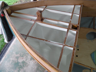
While I was painting the inside of the decks I wondered, more than once, how well the masking tape would work. Would it keep the paint off the gluelines or would I have paint creeping under the edges of the tape? Would it come off cleanly without pulling paint away? Here is a photo of the foredeck with the tape removed; there was no paint under the tape at all and the tape pulled off cleanly without taking any paint with it. This, to me, is a good recommendation for the tape (3M blue tape number 2080EL, $16 per roll! but it works) and the paint which sticks to itself and the underlying plywood very well).


Here is a pic of the bench with its collections of tins of paint and solvent. I started the painting using brushes and then experimented with a small foam roller 150 mm long and about 30mm diameter, it is the white phallic symbol. The roller has a rounded end and this works very well to wipe or smear paint into corners and areas that are too small for the roller to fit. It works very well for spreading the paint around quickly and copes with the plank overlaps very well. I use a brush for the really awkward places but the roller does the job for primer and undercoat in half the time. I put the finishing coats on with a brush and try to tip it all off in the same direction which can be tricky inside those compartments. The foam roller covers are cheap and I toss them rather than trying to reuse them. I use decent brushes and keep them clean for reuse.

Monday, 1 July 2013

Ballast Tank and Seat Tops

With the centreboard installed I glued the ballast tanks tops down; scratched the mating surfaces with 40 grit paper and applied lots of thickened epoxy and put the tops in place with quite a few kilos of concrete pavers to hold them down while the epoxy went off. Here's a photo, who needs ballast tanks when the boat's full of concrete pavers?


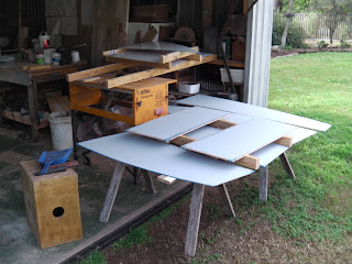
A few days later and there is now some paint, only primer at this stage, in the fore and aft compartments. I have shaped the ply deck panels and have been priming these at the same time. I tried to make the deck panels in one piece but gave up the struggle. The foredeck was particularly difficult because the deck is wider than the space between the gunwales so it had to bend quite a lot before it would go past the gunwales (and this is still without the inner gunwale in place). So I cut the deck panels in half arranging the join over one of the supporting beams. This will be OK but I would have preferred the panels to be in one piece.

I have also been working on the seat tops and, sad to say, I ran out of plywood with one panel to go! The photo below shows 5 out of six panels in place.. I had enough square millimetres of ply to make the last panel but it was in 3 pieces. I made the first of the scarph joints today and will make the second tomorrow. Not because I am too mean to buy another sheet of ply, but because I would spend 2 hours on the road buying the ply versus 30 minutes for the two scarf joints.

As an aside, it is winter here in Brisbane and so epoxy doesn't go off as quickly as in summer and paint doesn't dry as fast. This makes gluing more tedious because the epoxy doesn't want to be pumped up out of the containers (I put it in an old esky with a light bulb to warm it) but painting is easier because there is more time to lay off the finish coats.


Here are four photos showing the state of paly from different angles. The white inspection hatches in the front ballast tank tops will be replaced with new black ones. The white ones are there to keep the dust, dirt and shavings out for the time being.


Wednesday, 26 June 2013

Centreboard Installation

While I was sealing the ballast tanks with epoxy I realised that it would be much easier to install the centreboard before gluing down the tank tops. There are holes for inspection hatches to allow the pivot bolt to be removed/replaced but it seemed like a good idea to put it all together the first time without needing to use the inspection holes. As it turned out there wasn't a problem and I could have done it through the inspection holes. Here is a photo of the plate hovering over the centreboard case.


The board pivots on a  25mm diameter bronze sleeve with a 16mm 316 stainless bolt through it to keep it all in place. Here is the plate with the sleeve and bolt.


With the board in place the swage on the lifting shackle sits up above the top of the CB case as expected. This will need a clearance hole in the CB case top and a pad under the turning block that sends the lifting cable forwards.


Last photo shows the retaining bolt in place. As usual the bolt is 5mm too short so that the Nyloc nut doesn't have enough thread to get a grip on. This can be fixed easily through the inspection holes when the ballast tank lid is in place. also on show in this photo are the epoxy fillets and multiple sealing coats of epoxy on the inside of the ballast tank/

Monday, 24 June 2013

Floor Panels and Ballast Tank Tops

 
I am installing two removable floor panels aft of the centreboard case and two forward of it. These panels are supported by rails around the edges and will be held in place by the catches that I described in an earlier post. The first photo shows the aft panel on the port side. The finger holes allow it to be lifted. The outer edge will be held down by the rim of the inspection hatch and by a small wood block in the aft corner (not yet fitted).
 

Here are the two aft panels in place.


There are six ballast tank tops either side of the centreboard case. These are made from a different ply with a browner colour than the removable floor panels. There are holes in the forward panels for inspection hatches to be fitted so that the centreboard pivot bolt can be accessed if necessary in the future.


The last photo shows the air vent for the ballast tanks on the port side, there is a similar vent on the starboard side. When the boat is launched the black plug can be left in place; this will prevent air leaving the ballast tank and so not much water (if any) will enter through the open port in the bottom of the ballast tank. If the plug is removed water will enter through the bottom of the tank and push the air out until the tank is full. Putting the plug back in will stop the water running out. When retrieving the boat onto its trailer the plug is removed and the ballast tanks drain as the boat leaves the water.

 
At this stage the ballast tank tops are loose. Tomorrow the inside of the tanks will be given multiple coats of epoxy to seal them and then bedded down in thickened epoxy to fix them permanently in place.
 
June 26th, 2013. Here is an update to June 24th's post. Yesterday was a cold day and the epoxy was slow to go off so I didn't get as far as expected. I also realised that it would be sensible to install the centreboard while I still had full access for fitting the pivot bolt. The result is that the tanks are still open.
 
Here is another photo of the vent pipe. it is made up from 15mm PVC pipe and fittings. From left to right: a threaded end fitting with all but 9mm of the thread cut off, pipe, 90 degree elbow, 45 degree elbow, threaded female fitting and a black threaded plug.


Sunday, 16 June 2013

The Rudder

The rudder has been made up for some time and today I cleaned it up and did a trial run with the rudder gudgeons and pintles. Here it is fitted to the boat . The pie shaped piece is the drop down rudder blade which increases the underwater area.
 
 
I'm using a single long pin through the two sets of hinges and discovered that the trim strips on the transom prevented access for the pin. I have removed a scallop shaped piece of the trim strip so that the pin can be inserted and removed. Another problem was that the shoulders on the thick part of the rudder hit against the trim strips limiting the angle that the rudder can swing through to about 42 degrees either side of centre. I'm trying to decide whether that is enough or do I have to remove more of the trim strips to get 2 or 3 more degrees.


Here's another photo of the upper hinge.


With the rudder in position I wanted to get a feel for how long and at what angle the tiller needed to be. I like to sail standing up when possible  so the tiller needs to be a bit higher, Here it fits nicely in my hand.

Sitting down the tiller needs to be lower so I will arrange for a few degrees of movement to cater for these 2 positions.


I could have sailed the boat out of the shed and down the street! This photo, with me sitting in the boat, might give some idea of the overall size. I'm pleased to see that I wont need to duck as the boom goes over from side to side, it will clear my head with room to spare.