I'm writing this in the middle of a two week break from boatbuilding. Last week I went sailing with a group of guys from the Wooden Boat Association and had a great time. Tomorrow I'm off to Perth for a week visiting relatives and a friend.
The last thing I did on the boat was to make a template for the foredeck. It is made up off strips of scrap ply fixed together with hot melt glue. It is strong enough to withstand the pulling and pushing to get it off and on over the samson post. It remains to be seen whether the 9mm ply deck will be flexible enough to put into place. Here is a photo of the finished template.
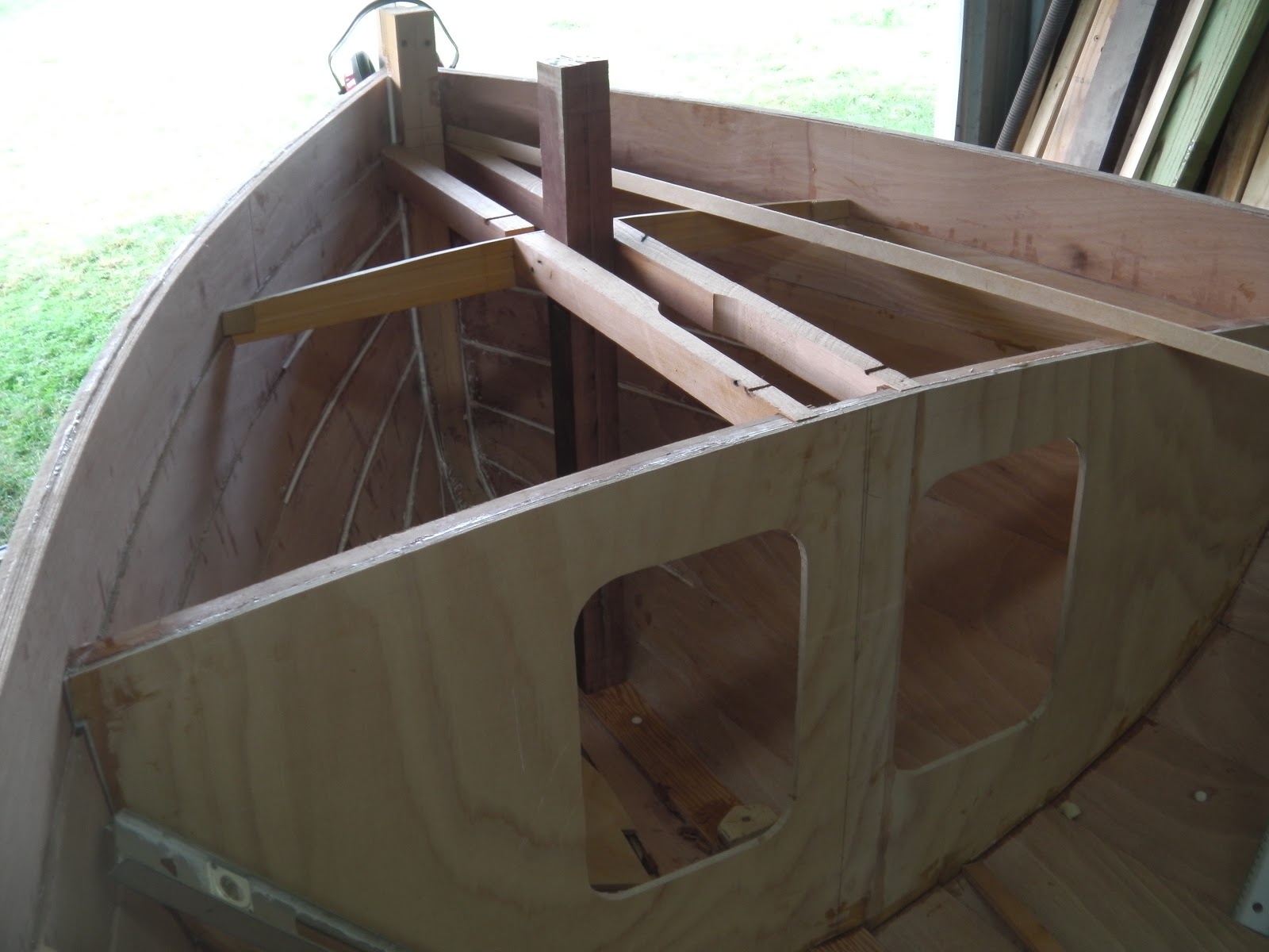
As it stands the interior of the boat is almost complete up to the level of the seat tops. There are 3 pieces of timber to glue in place, some cleanup to do and a lot of epoxy fillets to put in/ Once that is done I will start painting the inside of the various compartments before putting the tops on. Here are 3 photos of the interior.
I'm building a boat to a design by Paul Fisher of Selway Fisher Design in the UK. The design is called "Able" and her vital statistics are: overall length 4.88m (16ft), beam 2m (6ft 6in) and design weight is 360kg (790lbs). You can read more about this design at http://www.selway-fisher.com/OtherDB.htm#KANE.
I intend to procede more slowly with this boat than I did with either of my other boat building projects (see links below on the right). This is, after all, a hobby and there are other things to do. So, updates to this blog might happen once every week or two. Come back and see.
If you would like to contact me please Click to Send me Email
I intend to procede more slowly with this boat than I did with either of my other boat building projects (see links below on the right). This is, after all, a hobby and there are other things to do. So, updates to this blog might happen once every week or two. Come back and see.
If you would like to contact me please Click to Send me Email
Friday, 19 April 2013
Friday, 12 April 2013
Foredeck Beams and Bowsprit
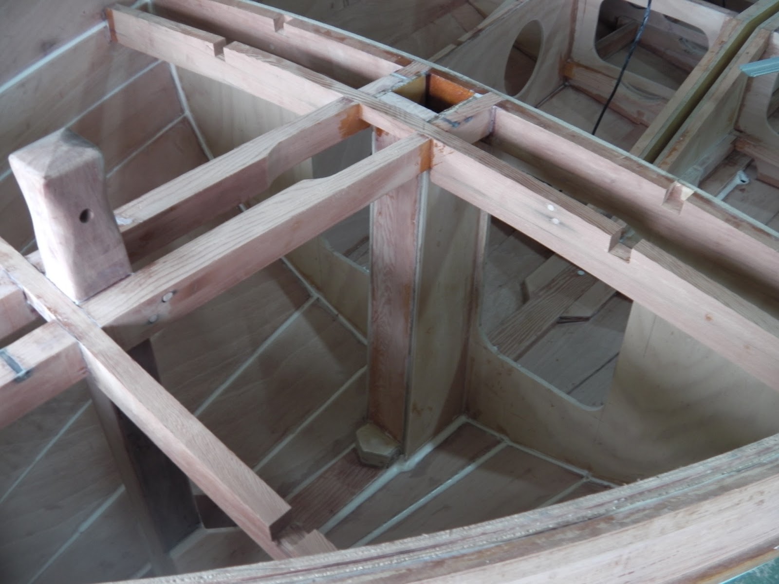
I have been cleaning up the beams that support the foredeck and gluing them in place. As this progresses it becomes harder to do anything in the space below the beams. I put epoxy fillets along all the plank seams and added the gussets to support the base of the samson post before fixing the beams. Here is a photo
There are still two fore and aft beams to add where the notches can be seen.
While working on these beams I have been thinking about the bowsprit. Today I made one up according to the plans, here it is.
I'm not sure that I like the way it is attached although I think it will work OK. An alternative approach would be to cut off the top of the stem and fit a longer bowsprit through a fixture on the stem head with the aft end of the bowsprit held in a block on the foredeck. Taking the bowsprit back as far as the samson post would need the samson post to be higher and this would look really strange. I will leave the bowsprit shown above in place and keep thinking about it.
There are still two fore and aft beams to add where the notches can be seen.
While working on these beams I have been thinking about the bowsprit. Today I made one up according to the plans, here it is.
I'm not sure that I like the way it is attached although I think it will work OK. An alternative approach would be to cut off the top of the stem and fit a longer bowsprit through a fixture on the stem head with the aft end of the bowsprit held in a block on the foredeck. Taking the bowsprit back as far as the samson post would need the samson post to be higher and this would look really strange. I will leave the bowsprit shown above in place and keep thinking about it.
Sunday, 7 April 2013
Folding Mast.
I am keen on the idea of a folding mast on my Able. The advantage I see with this is a dramatically reduced time to rig and pack up the boat. Here is a photo of a boat with the sort of folding mast that I envisage.
Nice boat isn't it, it is a Newport Lobster Boat belonging to Dave McCulloch.
To rig the boat the mast is pushed up into the vertical position and the forestay attached to the end of the bowsprit. The rest of the rigging, side stays, halyards, etc is already attached. The sail is unbundled and can be raised immediately. To pack up the sail is lowered and bundled around the boom. The forestay can now be released and the mast lowered and the boat is ready to go home. I expect the whole process or rigging or packing up to take 15 or 20 minutes instead of an hour or more.
For this idea to work the lower part of the mast has to be firmly supported so that it can't move. This can be done in several ways. It could be built in as a permanent part of the boat - this is probably the easiest solution but if it ever had to replaced some serious rebuilding of the boat would be involved. Another approach could be to step the mast on the keel and support it at deck level in a partner attached to the rear face of the large forward bulkhead. To do this the bulkhead would have to be moved forwards to maintain the correct position of the mast; the original design has the mast just in front of the bulkhead. Moving the bulkhead forward would reduce the volume of the forward buoyancy compartment and so this approach was abandoned. The approach adopted involves putting the base of the mast in a box inside the forward compartment. To keep the correct position of the mast the bulkhead has to move towards the stern by a few millimetres. As the top of the box would be open, allowing water to get in, it has to be sealed from the buoyancy compartment and drained into the cockpit.
To try and work out how this could be achieved I made a template showing the position of the mast and some of the supporting structure. Here it is in position behind the template for the bulkhead.
The photo below shows a closer view of the template, click on the photo to enlarge it.
At the top of the template you can see a horizontal pencil line across the 3 red lines. The intersection of the pencil line and the middle red line is where the pivot pin that supports the mast in the original design should be. This point has to be maintained on the centreline of the mast.
The 3 red lines on the template show the faces and centre of the mast at the correct rake (95 in 2000 or 38 in 800). Either side of the mast at deck level are the 65 x 25 deck beams.
The sides of the box will be 9 mm ply and the front and back will be 25 x 80. The geometry of the joints where the mast goes through the deck is going to be a bit tricky. The two fore and aft timbers that support the deck will need to be thicker than the design calls for because they go past the inner stem and samson post (65mm wide) and then come to the mast where they will have to be notched around the box (80mm for the mast and 2 x 9mm ply sides.
I will put a pad on top of the keel to spread the load from the mast a bit, the box sides will come down past it to meet the hull, all voids filled with epoxy!
In the next photo the finished bulkhead has been glued in place and the template showing the mast position put back in place. The block that the mast will stand on is visible at the bottom of the template.
The 2 longitudinal deck support beams have been fitted, below. The samson post is visible between them and the forward cross beam is in place. Note that the deck is cambered and the curve on the top of this beam is not the same as the curve across the top of the bulkhead, this is a trap for the unwary! None of these timbers has been glued in place yet.
The next photo shows all the framework in place but not glued. I made a dummy mast out of scrap ply with a taper representing the rake of the mast (95 mm in 2000 mm) and wedged it in place in the the mast supporting box. The spirit level shows that the mast slopes backwards at the correct angle. Yippee!
Here is a view ot the bottom part of the mast support box.
After making a start on gluing the pieces of the framework in place, this will take a while because each lot of epoxt has to set before the next joints can be glued, I made a startof the forward seat fronts. The template can be seen on the fqar side of the boat and the finished, but not glued, nearn side seat front is in place with its supporting stringers.
At this point there is a lot of gluing to be done, of parts that already made, and I have to go buy more plywood and Oregon (Douglas Fir) because I have completely run out of both.
Saturday, 30 March 2013
More on Bulkheads
I seem to be stuck on bulkheads but over the last couple of days the inside of the boat has started to come together. Making up the bulkheads on the bench seened to take a long time but once they are complete putting them in the boat has been very quick and easy. Putting the bare plywood bulkhead into the boat and then adding all the stringers to them would have been more difficult and I think it would have taken longer.
This is what the bulkhead looks like when it is being glued together on the bench.
Here it has been cleaned up and is in position in the boat for the glue lines to be marked out and taped. I was sceptical about the tape but it really does help to keep the epoxy under control.
This is what the tape looks like. The next step is to prime the glue line and the edges of the bulkhead with unthickened epoxy and leave it to soak in for a while. Then thickened epoxy is applied liberally between the lines of tape. What I'm trying to do is to ensure that the gap between the hull and the bulkhead is full of epoxy.
The next photo shows two of the four bulkheads in place. These bulkheads support the cross seat and brace the centre board case.
Today the second pair of bulkheads were installed in the boat. In between cleaning them up, taping and gluing them in I made templates for the aft side seat fronts and cut the ply panels. This last photo shows the state of play at the end of today's work.
There will have to be a pause in procedings because I have run out of ply and need to buy more (that can't be done at Easter!). Until then there is the supporting beams for the aft side seat tops to work on, more than enough to keep me busy until the shops open again.
Sunday, 24 March 2013
Ballast Tank Bulkheads
Before I get on to the ballast tanks here is a photo of the box that supports the mizzen mast. It is now glued in place but still has to have epoxy fillets run around the joints. The box is sealed at the bottom and any water that gets into it drains out through a hole in the transom.
I seem to be making very slow progress on the ballast tank bulkheads. There are two short ones at either end of the centreboard case and two taller ones that support the cross thwart. All four bulkheads have stringers glued to them to support the tops of the ballast tank compartments. When the bulkheads are in place the stringers have to be level so the top of the tank is flat. I decided to fit the stringers to the bulkheads on the bench because this is much easier and cleaner that glueing them to the bulkheads in the boat. The measuring and marking the position of the stringers has to be done in the boat and is awkward to do.
Here is a photo showing the two short bulkheads, one glued in place the other waining for the glue to set. The tops of these two bulkheads have to be level across the boat and also fore and aft. The stringers on the two intermediate bulkheads also have to be at the same level and so they can only be positioned when the first two are in place.
I seem to be making very slow progress on the ballast tank bulkheads. There are two short ones at either end of the centreboard case and two taller ones that support the cross thwart. All four bulkheads have stringers glued to them to support the tops of the ballast tank compartments. When the bulkheads are in place the stringers have to be level so the top of the tank is flat. I decided to fit the stringers to the bulkheads on the bench because this is much easier and cleaner that glueing them to the bulkheads in the boat. The measuring and marking the position of the stringers has to be done in the boat and is awkward to do.
Here is a photo showing the two short bulkheads, one glued in place the other waining for the glue to set. The tops of these two bulkheads have to be level across the boat and also fore and aft. The stringers on the two intermediate bulkheads also have to be at the same level and so they can only be positioned when the first two are in place.
Here is the template for the big bulkhead that forms the forward buoyance and storage compartment. The template is made from the building mould with short pieces of scrap ply hot melt glued to it to get the exact shape. I cut the centre out of the mould to lighten it.
Saturday, 16 March 2013
Stern Buoyancy/Storage Compartment
After turning the boat over the frame was removed and the boat set up on blocks so that it is well supported and level both fore and aft and across the beam. The next job was the tedious one of cleaning off the squeezed out epoxy from the plank laps on the inside. Some of the squeeze out I had removed once the plank was in place but there were places that I couldn't reach and bits I had simply missed.
With the hull cleaned up I started on the buoyancy and storage compartment in the stern of the boat. I used the building frame as a template with short pieces of scrap ply attached to make an exact fit with the inside of the hull. Here is a photo of the completed template still in the boat.
Several more jobs had to be done before the new bulkhead could be glued in place. A rail was fitted to the transom to support the rear edge of the top of this compartment and another rail was glued to the top of the new bulkhead to support the front edge. The position of the box that supports the foot of the mizzen mast was marked. In the next photo the new bulkhead is glued in place; the 4 strips are scrap ply braces to hold in in position while the glue sets.
In between the cutting and shaping of the template and the new bulkhead I made up the box that holds the foot of the mizzen mast. This is a simple box, 4 sides and a bottom but I found it quite tricky to make. The plywood sides need to be shaped to fit the bottom planks of the hull. The front, back and bottom of the box are solid timber. I glued the five pieces together 2 at a time. First the front and bottom. Then the ply sides, one to the front and one to the back. Then finally the last 2 sections were glued together as shown in the following photo. It is hard to see the box past all the clamps holding it together. The last sections of the box were given 3 coats of epoxy before the final gluing and the inside of the box will be painted before the top is fixed on the compartment. Once the top goes on the inside of this box will be inaccessible.
Because water can get into the box around the mizzen mast there has to be a drain hole through the transom. The hole can just be seen in the photo above, towards the top left of the hatch opening - click on the photo to enlarge it. Like the ballast tank holes in the bottom of the boat, described in an earlier post, this hole has a plastic sleeve epoxied in the hole. This sleeve will protect the edges of the hole and provide a better seal of the endgrain inside the hole.
The last of today's photos shows the template for the next bulkhead working forwards. This bulkhead is in 2 halves separated by the centreboard case and, together with another similar pair of bulkheads about 400 mm forther forward provides the vertical faces of a compartment that stretches across the boat.
Tuesday, 5 March 2013
Turning Over Ceremony
Today was the big day! My Able is now the right way up. I rounded up 8 volunteers from the Queensland Wooden Boat Association plus my daughter and son in law. Thanks to all of you for making the effort to come and help. I hardly needed to take part and also had a photographer. Here is how it went.
Still in the shed with wheels fitted to corners of frame. Ready to go.
Out on the grass, wheels on the low side have been removed and added to the top of the frame on the high side. The frame is propped up while the other pair of wheels are removed.
Starting the lift towards the vertical.
Almost up to the halfway point.
Halfway point.
On the way down. Gently lowered onto the wheels.
Back on the wheels on one side.
Tipped up with frame on saw horses while the second pair of wheels were added. After the boat had rolled over through 180 degrees it was displaced sideways by almost 4 metres. This photo was taken after we lifted the whole thing up and moved it sideways to line up roughly with the space in the shed.
Back in the shed. Thanks again to the volunteers who made it so easy.
Subscribe to:
Posts (Atom)